Residual Stresses and Mechanical Damage in Gas Pipelines
Thomas Gnaupel-Herold1,2, Remy Batisse3, Lynann Clapham4
1University of Maryland, Department of Materials Science and Engineering
College Park MD 20742
and
2Center for Neutron Research, National Institute of Standards and Technology
Gaithersburg MD 20899-6102
3GDF SUEZ, Transmission Technologies Section
361, Avenue du President Wilson
93211, Saint-Denis la Plaine, FRANCE
4Queen's University, Engineering Physics Department
Kingston, Ontario, K7L 3N6 Canada
Construction or agricultural activity is a main cause for mechanical damage in pipelines. If there is no immediate rupture then a crucial question arises: How critical is the damage and what actions need to be taken? In order to address the latter the damage has to be quantified in some manner, and Magnetic Flux Leakage (MFL) is one of the tools the industry uses for that purpose. In this method a MFL probe records changes in the magnetic field between two magnetic poles that are in close contact with the pipe wall. Dents and gouges create changes in geometry, plastic strains and residual stresses; all of which severely alter the MFL signal in ways that are not completely understood. Geometry changes are more readily quantifiable but the residual stress contribution is difficult to determine due to the lack of experimental data and reliable modeling results. Some progress has been made by annealing the sample, thus eliminating the residual stress contribution [2]. However, this cannot address questions about the role of the multiaxiality of stresses, sign changes of stresses and stress gradients, both laterally and through the thickness [3]. Thus, it is necessary to measure the residual stresses non-destructively which requires neutron diffraction as the only technique capable to handle pipe sections due to problems of weight, dimensions and wall thickness.
 It is obvious that, in order to
put such measurements on a sound footing, one cannot wait for such damage to
occur, then remove that pipe section, and perform the necessary measurements.
Instead, the various type of gouges and dents that are encountered on real
pipelines need to be produced in a controlled and repeatable fashion. By
varying the testing speed, the deformation path, and the tool shape it is
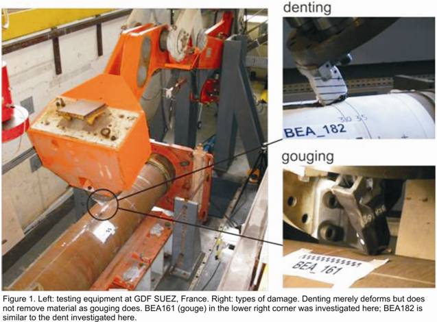
possible to cover a wide range of real-world damage scenarios (Figure 1) that
combine the two major elements of gouging (removes material, has some plastic
deformation) and denting (plastic deformation only).
It is obvious that, in order to
put such measurements on a sound footing, one cannot wait for such damage to
occur, then remove that pipe section, and perform the necessary measurements.
Instead, the various type of gouges and dents that are encountered on real
pipelines need to be produced in a controlled and repeatable fashion. By
varying the testing speed, the deformation path, and the tool shape it is
possible to cover a wide range of real-world damage scenarios (Figure 1) that
combine the two major elements of gouging (removes material, has some plastic
deformation) and denting (plastic deformation only).
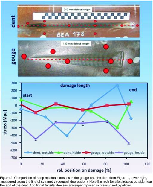
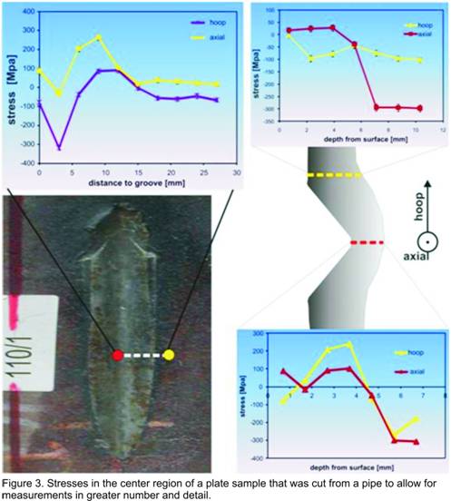
Figure 1 illustrates the unique challenges to the stress measurement presented by this approach: First, the damage regions with 300 mm dent length (see 30 cm mark in Figure 1, upper right corner), and 130 mm gouge length, respectively, are unusually large. Second, the pipe should stay intact circumferentially, and retain sufficient length axially as much as possible in order to preserve the stress field. The resulting samples were pipe sections 650 mm in diameter, 500 mm in length, and 8 mm wall thickness. The wall thickness is quite low, and in order to sample the stresses in sufficient detail through the thickness the spatial resolution of the measurement – in other words, the size of the neutron beam – must be chosen appropriately (here: 1 mm). Aside from some basic symmetry considerations – e.g. the stress field is presumed to be laterally symmetric – there is not much one can assume about the stresses, thus creating the necessity for measurements at numerous locations in the defect area and through the thickness. As shown in Figure 2, measurements along the line of symmetry show that the stresses created by the two defect types exhibit significant changes in magnitude particularly near the start and end of the defects. The high tensile hoop stresses near the end of the dent are a red flag because the total stress in a pressurized pipeline– residual stress plus stress from pressure – may reach the tensile strength of the material. The danger of pipe rupture arises if the high stress levels are combined with a weakened cross section at the location of the peak stress due to large strains (dent) or material removal (gouge). However, the stresses must also be considered in the context of MFL measurements, particularly in view of the lateral resolution of MFL probes which can be of the order of 1 mm. The MFL signal is a weighted average through the thickness, which is why it is difficult to assign a depth location to a sub-surface defect. Rather, the interplay of gradients in different directions creates a cumulative effect where different combinations of stresses can produce the similar MFL signals. Thus, the contribution of different through-thickness stress gradients to MFL signals is of particular interest. As shown in Figure 3 stress gradients near the surface are most severe in the lateral direction away from the defect where over a length of 5 mm stresses change by more than 300 MPa. The stress differential in the radial direction (through the thickness) is of similar magnitude. \
 Aside from aiding the
interpretation of signals from MFL probes these findings also help in
addressing safety concerns. Pressure in a pipeline superimposes a stress on the
residual stresses, and the total stresses should not exceed certain limits set
by the safety factor (between 1.5 and 10). What problems could arise if
creating the mechanical damage in the pipes did not cause immediate pipe
rupture? On one hand, these limits are exceeded in pipelines with low safety
factors both in regions of peak tensile stresses and where the cross section is
reduced the most. On the other hand, the mechanical damage creates work
hardening which raises the strength locally. The end result could be viewed as
a locally reduced safety factor that in extreme cases may require the reduction
of the operating pressure in the pipeline. Another damage-related problem to
consider is the increased risk of stress corrosion cracking assisted both by
high tensile stresses and coating failure in the dent/gouge region.
Aside from aiding the
interpretation of signals from MFL probes these findings also help in
addressing safety concerns. Pressure in a pipeline superimposes a stress on the
residual stresses, and the total stresses should not exceed certain limits set
by the safety factor (between 1.5 and 10). What problems could arise if
creating the mechanical damage in the pipes did not cause immediate pipe
rupture? On one hand, these limits are exceeded in pipelines with low safety
factors both in regions of peak tensile stresses and where the cross section is
reduced the most. On the other hand, the mechanical damage creates work
hardening which raises the strength locally. The end result could be viewed as
a locally reduced safety factor that in extreme cases may require the reduction
of the operating pressure in the pipeline. Another damage-related problem to
consider is the increased risk of stress corrosion cracking assisted both by
high tensile stresses and coating failure in the dent/gouge region.
These measurements are part of an ongoing international project in which different pipeline defects are produced under realistic conditions, and then characterized with respect to residual stresses and MFL signal distribution. The neutron diffraction measurements are the first of this type and they revealed complex stress patterns both through the thickness and in the lateral directions. It is one of the goals of these efforts to use the neutron data in order to create a functioning magnetic model that allows the separation of the geometry effect and the stress effect on the magnetic flux leakage signal, thus greatly enhancing the scope of MFL probes as an in-line inspection tool.
References
[1] [1] Pipeline Performance in Alberta 1980-1997, Alberta Energy and Utilities Borad 1998, available at: http://www.eub.gov.ab.ca
[2] [2] L. Clapham et al., Proc. 2004 Int. Pipeline Conference, Calgary 2004, 983-990
[3] P.A.Ivanov et al., IEEE Transactions on Magnetics, 34, 3020 (1998).