Two changes made to the optics of the C H R N S 30-m SANS instrument during the installation of the N C N R’s new cold source have increased the flux at the sample and the low-Q resolution of the instrument.
The increase in flux, over and above that provided by the new cold source, comes from replacing the instrument’s cooled bismuth-beryllium filter with an “optical filter” of the type shown schematically in Figure 1. The optical filter replaces 10 meters of straight neutron guide and its 40 centimeters long bismuth-beryllium filter with an inclined guide section with a high critical angle supermirror reflective coating. The optical filter channels cold neutrons, with wavelengths as short as 3 angstroms, out of the line-of-sight of fast neutrons and gamma rays from the source. The cold neutrons delivered to the S A N S instrument undergo an even number of reflections in the optical filter to emerge in the horizontal direction, but displaced 14 centimeters vertically. To accommodate the beam displacement, the entire S A N S instrument had to be raised; a non-trivial task that required detailed engineering analysis, careful planning and skilled execution.
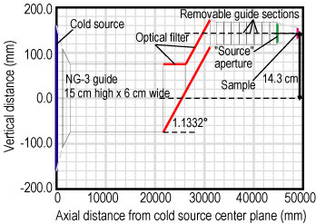
| Figure 1. Schematic elevation of the N G 3 optical filter (note vertical scale is exaggerated for clarity). The inclined section shown in red is coated with supermirror with critical angle approximately 3.2 times that of natural nickel. The removable guide sections are in the pre-sample flight path of the N G 3 S A N S instrument. |
The design of the optical filter was refined with the aid of detailed Monte Carlo calculations of the angular and spectral distribution of neutrons transmitted by the optical filter. Figure 2 shows the calculated and measured gain in flux at the sample, due to the optical filter alone, for the supermirror reflectivity model shown in the inset. These results demonstrate that the optical filter transmission is about the same as the previous crystal filter for wavelengths around 5 angstroms, but becomes substantially better at longer wavelengths where absorption in the crystal filter becomes significant.
The optics for the C H R N S, S A N S instrument were further improved by installing a system of refracting lenses and prisms near the sample position to focus 17 angstrom neutrons onto the detector at its maximum distance, 13 meters, from the sample. A similar lens system, consisting of 28 biconcave single crystals of magnesium difluoride for focusing 8 angstrom neutrons, has been in use on the N C N R’s other 30 meter S A N S instrument on guide N G 7 for nearly two years (Refer to reference 1). The refracting power of the lenses increases with the wavelength squared, but so does the distance the neutron falls between the sample and detector due to gravity. The vertical spreading of the focus for a beam with a wavelength spread typical of a S A N S instrument, about 10 % to 15 % F W H M, restricts the utility of the lenses alone to wavelengths less than 10 angstroms. The new development implemented on the C H R N S, S A N S instrument is to follow the lenses with prisms that refract in the vertical direction to counteract the effect of gravity.
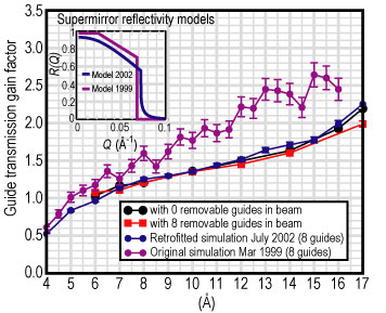
| Figure 2. Transmission gains of the N G 3 optical filter. The black circles are measured with no removable guides in the beam. The red squares are measured with 8 removable guides in the beam. The violet circles are the original Monte Carlo simulated gain predictions (March 1999) using the supermirror reflectivity model shown in the inset. The blue circles are simulated gains (July 2002) using the refined reflectivity model shown in the inset. These “hindsight” simulations predict the measured gains well for M = 3.2 supermirror with R, open parenthesis, Q = 0, close parenthesis, = 0.930 and R M S surface roughness equal to 10 angstroms with R, open parenthesis, Q = 0.069 inverse angstroms, close parenthesis = 0.55. |
Figure 3 depicts the arrangement of lenses and prisms now installed on the C H R N S, S A N S instrument. Seven magnesium difluoride biconcave lenses focus 17 angstrom neutrons at the detector, 13 meters from the sample. For this distance a single prism with an apex angle of 161º would cancel the beam spreading due to gravity for all wavelengths (Refer to reference 2). Such a prism, however, would have to be 250 millimeters long at its base to intercept the full beam height transmitted by the lenses (approximately 2 centimeters). A more practical scheme, as shown in Figure 3, is to stack two sets of prisms, with each prism 30 millimeters long and 5 millimeters high with an apex angle of 143º, to give the same anti-gravity effect. In this scheme, the bottoms of each prism are coated with gadolinium oxide to eliminate surface reflections.
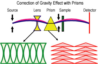
| Figure 3. Schematic diagram of the configuration of lenses and prisms used on the 30 meter C H R N S, S A N S instrument. The seven biconcave lenses focus 17 angstrom neutrons at the detector, 13 meters from the sample, and the double stack of prisms refracts the beam vertically to cancel the effect of gravity. |
The effectiveness of the lens/prism combination can be seen in Figure 4 that compares circularly averaged S A N S data from voids in an irradiated crystal of aluminum obtained with pinhole collimation and with the focusing optics. The data for the lens/prism system extend to a minimum scattering vector Q = 0.00045 inverse angstroms, nearly a factor of two lower than the pinhole collimation. Furthermore, the scattered intensity is 3 times higher with the lens/prism system because a larger area of the sample can be illuminated without degrading the Q-resolution. With pinhole collimation, intensity at the detector is roughly proportional to Q to the power 4, sub m i n, hence the lens/prism system represents an overall intensity gain of 48 compared with simply reducing pinhole aperture size to achieve the same minimum Q.
The new cold source and improvements in optics are enabling microstructural studies that link nanoscale with microscale features in, for example, polymer-clay nanocomposites, gels, and fluxoid lattices in superconductors.
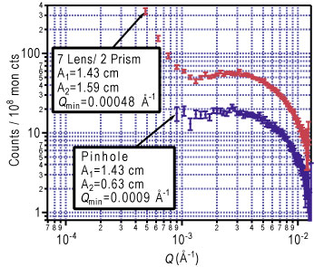
| Figure 4. S A N S from voids in an aluminum crystal measured with and without the new focusing and gravity cancellation optics installed on the C H R N S, S A N S instrument. The optics halve the minimum accessible Q-value while increasing the scattered intensity roughly threefold. |
References
[1] S.-M. Choi, J. G. Barker, C. J. Glinka, Y. T. Cheng, P. L. Gammel, J. Appl. Cryst. 33, 793 (2000).
[2] E. M. Forgan, R. Cubitt, Neutron News 9(4), 25 (1998).
Authors
J. Cook, I. G. Schröder, S. R. Kline, B. Hammouda, and C. J. Glinka
NIST Center for Neutron Research
National Institute of Standards and Technology
Gaithersburg, MD 20899-8562
Sung-Min Choi
NIST Center for Neutron Research
Present affiliation:
Korea Advanced Institute of Science and Technology
373-1, Guseong-dong, Yuseong-gu, Daejon,
Republic of Korea 305-701
Back to FY2002 HTML main page
Go to next article
To view all symbols correctly, please download Internet Explorer 6 or Netscape 7.1