The 14 cold neutron instruments at the N C N R received a substantial increase in performance when the liquid hydrogen cold source, successfully operated since 1995 (hereafter called “Unit 1”), was replaced with an improved design (called “Unit 2”) during last year’s maintenance outage. The N C N R cold source is designed to maximize the useful intensity of neutrons in the wavelength band between 0.2 nano meters and 2.0 nano meters by providing a low temperature medium that further slows down the neutrons exiting the heavy water moderator/reflector of the N I S T 20 mega watt reactor. The basic operating principles for the cold source are the same in both designs (Refer to reference 1). Using the large diameter cryogenic beam port at the N C N R reactor, a cryostat containing a thin, annular shell of liquid hydrogen is placed in a high intensity region of the reactor’s reflector. Interaction with the slow moving hydrogen molecules modifies the neutron energy spectrum. A neutron guide tube system beginning close to the exit of the cryostat transports the intense cold neutron beams to the neutron scattering instruments. The radiation heat deposited in the moderator is removed by boiling of the liquid hydrogen. Stable operation of the cold source is maintained by a thermo siphon; cold liquid hydrogen flows by gravity into the cryostat from a helium cooled condenser and the hydrogen vapor from boiling returns to the condenser in a closed, convective circulation loop. The cryostat also includes a heavy water cooling jacket, insulating vacuum regions and helium containment vessel that surrounds all portions of the system containing hydrogen.
Following the commissioning of Unit 1, detailed simulations of the N C N R reactor and moderators became sufficiently accurate that it was possible to explore further optimization of the cold source geometry for improved performance using a sophisticated M C N P model of the N C N R source (Refer to reference 2). The Unit 2 design differs from Unit 1 in many key respects, as can be seen in Figure 1. Most of the volume of the Unit 1 cryostat assembly was empty space, leaving a large void in the reactor reflector and lowering the neutron flux near the cryostat. The heavy water cooling jacket of Unit 2 was expanded to fill nearly half of the insulating vacuum void of Unit 1. This change reduced the void in the reflector and increased the neutron flux near the cryostat by about 40 % thus providing a cold neutron gain of the same magnitude. Because of these changes and to fully illuminate the rectangular aspect ratio of the N C N R guide system, the Unit 2 moderator chamber is smaller than the original and is an ellipsoidal annulus, rather than a spherical one. With a smaller vessel size, the thickness of the liquid hydrogen shell could be increased from 20 milli meters to between 25 milli meters and 30 milli meters without increasing the overall hydrogen inventory. Finally, the inner ellipsoid of the newer design is evacuated through a small vacuum port, removing most of the hydrogen vapor. In Unit 2, the cold neutron beam passes through only 20 milli meters of vapor, rather than through the 300 milli meter path length in Unit 1. This results in less neutron adsorption by hydrogen. Collectively, these changes in the moderator chamber add another 15 percent to 20 percent to the predicted gain.
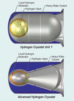 |
Comparison between the original (top) and the advanced liquid hydrogen cold sources for the N I S T research reactor. The heavy water volume is indicated in blue, liquid hydrogen in orange, and hydrogen vapor in yellow |
The complex geometry of Unit 2 posed many challenges for the design and fabrication of the cryostat. Complicated elliptical vessels were designed with the aid of finite element analysis to model their mechanical strength. Extensive pressure testing supported this detailed modeling. Because of the non-standard shapes, components were precisely cut from solid blocks of Aluminum 6 0 6 1 using a high-speed mill at the NIST instrumentation shop. The geometry also placed high demands on the welding of the various components into a leak-tight cryostat satisfying stringent quality control tests. The entire cryostat system was completely fabricated, assembled, and tested at N I S T. The replacement of Unit 1 with the new design was also a significant technical challenge. Detailed work planning was required to ensure that the highly radioactive Unit 1 could be safely removed with the least amount of disruption to the sensitive alignment of the neutron guide network. Radiation damaged neutron guides near the source were also systematically replaced during the installation. The installation was completed on schedule with a minimal dose exposure to the installation team.
When the reactor resumed normal operation on March 6, 2002, the thermal and neutronic performance of the new cold source was tested. Startup tests measured the helium refrigerator heat load as reactor power was increased. At 20 mega watts, the heat deposited in the source was measured at 1300 watts in excellent agreement with calculations. The cold neutron flux was monitored to ensure that the thermo siphon functioned smoothly and that the moderator volume remained full of liquid hydrogen as the evaporation rate increased to over 3 grams per second at full power. Further tests established the normal operating parameters for the cryostat and verified the protection systems under various abnormal conditions.
The performance of the new source was benchmarked against Unit 1 by duplicating flux measurements of the intensity as a function of neutron wavelength at several Guide Hall instruments. Figure 2 is a plot of the cold source gain, defined as the ratio of intensities between Unit 2 and Unit 1, as a function of neutron wavelength. The figure includes both the gain factors measured at three spectrometers and as obtained from the M C N P Monte Carlo simulations (Refer to reference 2). While the agreement is excellent, the measured gains were actually somewhat greater than predicted, especially at long wavelengths. This additional gain is likely due to the new guide sections replaced during the cold source installation, an effect that is not included in the M C N P models. The new cryostat design also substantially reduces the number of fast neutrons from the cold source resulting in improved instrument signal-to-noise levels.
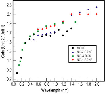 |
Gains in cold neutron flux measured at the N G 7 and N G 1 small angle neutron scattering (S A N S) instruments, and at the disk chopper spectrometer (D C S) on N G 4, compared to the predicted gains, based on Monte Carlo simulations using M C N P. |
The advanced liquid hydrogen cold source has successfully met all of its design goals. Its success demonstrates how the effective use of detailed computer models to optimize a design can lead to substantial performance improvements. However, it also demonstrates that the complex geometry that results from such an optimization requires more complex stress modeling, new fabrication technologies and even more stringent quality assurance testing. Most importantly, the success of the Unit 2 cold source design significantly enhances the measurement capability of the cold neutron scattering instrumentation at N I S T with intensity gains of nearly a factor of two in the important long wavelength region of the spectrum.
References
[1] R. E. Williams and J. M. Rowe, Physica B 3 1 1, 1 1 7 (2002).
[2] J. F. Briesmeister (Editor), M C N P – A General Monte Carlo N-Particle Transport Code, Version 4 B, Los Alamos National Laboratory, L A 1 2 6 2 5 M, Los Alamos, New Mexico (1997).
The Staff
N I S T Center for Neutron Research
National
Institute of Standards and Technology
Gaithersburg, Maryland 2 0 8 9 9 8 5
6 0
Back to FY2002 HTML main page
Go to next article
To view all symbols correctly, please download Internet Explorer 6 or Netscape 7.1