
|

|
|
| Home | Live Data | Instruments | CHRNS | Proposals |
EXPGUI top Next page
(EXCLEDT)Previous page
This page documents the LIVEPLOT and BKGEDIT utility programs in the EXPGUI package. LIVEPLOT and BKGEDIT are actually the same program, but perform different functions, depending on how they are invoked. LIVEPLOT is used to display the quality of the diffraction fit, while BKGEDIT is used to fit a background function to fixed background points that have been input by the user.
EXPGUI Utilities (1),
LIVEPLOT and BKGEDIT
Both LIVEPLOT and BKGEDIT get the current diffraction information by running the GSAS TCLDUMP program, if installed, or the GSAS HSTDUMP otherwise. The TCLDUMP program has been optimized for use with LIVEPLOT and allows LIVEPLOT to offer a number of extra options that are not available when HSTDUMP is used. Since TCLDUMP has been included in GSAS since April of 2000, the following documentation assumes that TCLDUMP is installed.
LIVEPLOT
LIVEPLOT is started by pressing the LIVEPLOT button on the toolbar or via the Graphs/liveplot menu item.Some of the features available in LIVEPLOT are:
- The plot is updated automatically after each refinement run
- The plot can be "zoomed-in", by clicking on the corners of the area to be magnified and "zoomed-out" using the right mouse button (Mac: Apple+click)
- The units used for plotting histograms can be selected. Choices are: native units (2Theta/TOF/KeV); d-space (A) or Q (A-1)
- The background (fixed plus fitted) can be plotted or can be subtracted.
- Reflection tickmarks can be displayed in a variety of formats
- LIVEPLOT can be coupled to the LOGIC or CMPR programs, so that peak positions for an arbitrary unit cell and spacegroup can be shown superimposed on the "Rietveld plot."
- Reflection indices (hkl values) can be shown for tickmarks
- The cumulative chi2 function or
(obs-calc)/sigma can be plotted.
- The cursor position can be displayed
- Plots can be exported to obtain publication-quality graphics.
BKGEDIT
BKGEDIT is used to fit a background function to a set of points selected by the user. For most refinements, this is not needed, as it is possible to simply select a background function (I find that the type 1 function, shifted Chebyschev polynomials, works well) and then refine, adding terms until a good fit is obtained. On occasion, poor initial fits are obtained in this manner. This is most common in cases where large numbers of peaks are poorly fit. Since significant sections of the data are not well fit, the refinement results in an unreasonable background function, because this yields better agreement with the observed data. In these cases, it may be best to fix the background to follow a "reasonable" curve in the initial stages and then refine the background in the final stages of refinement, when a good model has been obtained.
The BKGEDIT program, as shown below, is used to input a set a background points via the mouse. The points are then used to determine a type 1 (Chebyschev) background function that fits the input background points. These terms can then be saved in the experiment file creating a background that is good enough for the initial stages of refinement and that can be refined once the model is adequate for the task.
BKGEDIT can be used to fit GSAS background functions 1-6 (though for most purposes only type 1 is needed.)
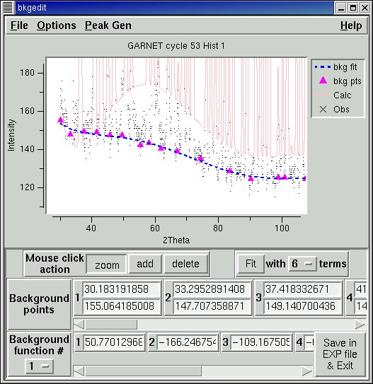
Steps in fitting a background function
The BKGEDIT program is started from via the Powder/bkgedit menu item or by pressing the "Fit Background Graphically" button on the "Edit Background" dialog box (invoked from the "Edit Background" button on the Histogram pane.) toolbar or
- Zoom in on the lower intensity section of the plot, so that the background is clearly discernible. In some cases, the data will need to be handled in sections.
- Press the "Add" button to add background points. Note the cursor changes from cross-hairs to an arrow, when the "Add" button is pressed.
- Move the mouse to the first location where a background point will be added and click with the left mouse button. A magenta triangle will appear at the location. Points can be added in any order. It is best to make sure that the fixed points are placed over the entire range of the data, e.g. near the maximum and minimum data points in TOF, 2theta, etc.
As background points are entered, they are saved in a file named EXPNAM.bkgN, where EXPNAM is the experiment name and N is the histogram number. If BKGEDIT is restarted at some later time, these points are reread.
Note that it is advisable to place many background points in areas where the background is changing rapidly (where the background is most bumpy).
- If any points are placed in incorrect positions, they can be deleted by pressing the "Delete" button. The mouse cursor changes to a circle. When the mouse left clicked, the fixed background point closest to the mouse position (which may be outside the zoom range) is deleted.
- Background points can also be edited by entering numbers into the "Background points" area.
- After enough background points have been entered, the "Fit" button turns from gray to black. When pressed, the selected background function is fitted and the resulting curve is shown as a blue dashed line.
- It is suggested that you start with relatively few terms and add terms and background points as needed. Note that the maximum number of increases as more background points are entered.
- Editing the terms manually is possible. The curve is reevaluated as changes are made.
- For the type 3 background function (radial distribution function), the R terms are listed separately from the other background terms. These R (radii) values must be entered manually and are not refined.
- Once a good background function is determined, it can be saved in the experiment file by pressing the "Save in EXP file & Exit" button. This will set the background type, and save the terms. It will also turn off the background refinement flag for the appropriate histogram so that the terms are not refined inadvertently.
Note that POWPREF must be run at least once before BKGEDIT can be used, however, use of GENLES before BKGEDIT is optional. If the data range is changed, for example by excluding a section of the data at the lower end, or changing tmax (dmin), the Chebyschev polynomial terms must change to generate the same background values, so both POWPREF and BKGEDIT should be rerun to regenerate the Chebyschev terms.
Why not use fixed background points?
I personally feel that a refined background function is preferrable to use of a fixed model, if at all possible. One reason for this is that Rietveld refinements usually achieve better fits when the background is optimized. A second reason refining the background provides a feel for the interaction between background values and displacement (thermal) parameters. Usually, background and displacement parameters are fairly independent, but for some materials, where the high Q (high 2theta) portion of the pattern has many completely overlapped peaks, it is impossible to uniquely determine where the background should be placed, either by refinement or by manual placement. Under these circumstances, the background should be refined with the displacement parameters fixed at an appropriate value for the material. The background should then be fixed for all future refinements and the displacement parameters can then be refined. Of course this means you have predjudiced the refinement to result in the expected average displacement parameter and this must be noted any publication. However, if this is necessary, the data simply do not contain sufficient information to independently determine background and displacement parameters. Use of fixed background points would not demonstrate this and would lead the researcher to a false sense of security (or fear, if the values are unreasonable) that the displacement parameters actually mean something.If you still want to use fixed background points, despite this tirade, be sure to set the estimated error on those points to be 0.0. Use of non-zero estimated errors, can result in artificially lowered R-factors and chi-squared values. In one test, I was able to lower the Rwp and reduced chi2 values, from the correct values of 0.042 and 3.0, respectively, to misleading values of 0.036 and 0.8, respectively. [As expected, the R(F2) stayed constant at 0.045 with the different fixed background errors; FYI, refining the background caused R(F2) to drop to 0.036, so I would consider the refined background to be better.]
If the background is so truly irregular that only use of fixed background points will do, BKGEDIT can be used to generate these fixed background points. The file used by BKGEDIT to save these points, EXPNAM.bkgN, will define the background points if read directly into EXPEDT by typing "@R" at the initial prompt in EXPEDT:
Is this the file you wish to use? (?,D,K,Q,R,Y) >@rprompt and then supplying the name of the file, in response to the next prompt:Enter the name of your macro file: GARNET.bkg1Doing this will cause the background points you entered into BKGEDIT to be used in GSAS fixed background points. If you do this you do not want to save the fitted background function as well, as this would effectively subtract double the desired background. Note that GSAS allows simultaneous use of both fixed and a refined background; this is seldom done.LIVEPLOT/BKGEDIT Features
Plot contents: Reflection markers can be placed using the File/Tickmarks menu itemor by pressing the "1" key for phase 1, "2" for phase 2,... Note that many attributes for reflection markers can be edited using Options/Configure Tickmarks
If more than one histogram is available to plot, it is possible to cycle between the histograms by pressing the "n" or "N" (for next) key.
Plot zooming: When the left (usual) mouse button is pressed, this defines one corner of a region to be magnified, as is shown to the right. If the mouse is then moved, the diagonal corner of this magnification region is defined. When the left mouse button is pressed a second time, the selected section of the plot is magnified to fill the entire plot.
Zoom settings are saved. If the right mouse button is pressed, the previous zoom setting is used, so that the left mouse button is used to "zoom in" and the right mouse button is used to "zoom out." Note, on the Macintosh, hold down the Apple button while using the [only] mouse button to simulate a right-click.
Zoom settings can also be entered manually by pressing the "Z" key. This opens a dialog, as is shown to the right, where the x- or y-axis range can be specified. Any value that is not specified is set to the maximum or minimum for the entire dataset. It is possible to zoom further in using the mouse, but to zoom out beyond the manual zoom limits, the "reset" button on the manual zoom menu must be used.
To shift the zoom region around, the right and left arrow keys can be used to shift the region 10 % to the left or right. Likewise, the up and down arrow keys can be used to shift the region up or down by 10 %. Holding down the control key down while pressing these keys increases the amount of the shift to 100 %.
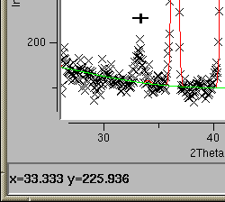
Cursor Display: Pressing the "L" (or "l") key, or using the Option/Show Cursor Position menu button causes the position of the cursor (mouse position) in plot to be shown. The coordinates are listing in a small area below the plot. The position display is updated as the mouse is moved. The same key, menu button, or the button labeled "Close cursor display" can be used to remove the display.
Features in LIVEPLOT only
The cumulative chi2 function was first suggested by Bill David as a way to see which reflections have the greatest influence on chi2 [W.I.F. David, Accuracy in Powder Diffraction-III, 2001]. It is defined for point j as
where yobs,i and ycalc,i are the observed and computed data points and sigmai is the expected error. Thus, the statistically expected value for [(yobs,i-ycalc,i)/sigmai]2 is 1 and this function should rise in a smooth line if all points are fitted as statistically expected. This can be displayed using the "Cumulative Chi2" item in the Options menu.
In the plot to the right, the cumulative chi2 function is shown in purple. Note that first peak is not well fit, but the low angle "shoulder" is as important as the peak misfitting, with respect to the chi2.
Plotting (Obs-Calc)/Sigma A more traditional way to see the data points that have the worst agreement between observation and model is to plot the difference between these values, but weighted by the reciprocal of the expected uncertainty, e.g. (yobs,i - ycalc,i)/sigmai, as defined above. The standard plot of (yobs,i - ycalc,i) over-emphasizes minor discrepancies in strong peaks while being insensitive to very significant discrepancies in weaker peaks, so the (yobs,i - ycalc,i)/sigmai is the more valuable plot. This can be displayed using the "(obs-calc)/sigma" item in the Options menu.
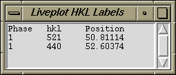
Reflection indices are be displayed by pressing "H" or "h" while the mouse is near a reflection (holding the shift key while pressing the left mouse button also works, but sometimes interferes with the zoom feature). Pressing "A" or "a" shows all reflections in the displayed region. The indices are shown on the screen for phases with tickmarks (as shown to the right). Indices are listed in the "Separate window for hkl labels" (as seen below) for all phases, regardless of the tickmark settings. Displayed indices will remain on the screen for a preset time and then will be deleted; alternately, pressing "D" or "d" deletes the hkl labels. Several aspects of reflection labeling can be customized, see the HKL labeling options for further information.
- The plot can be exported to Grace, WYSIWYG 2D plotting tool for X-Windows that produces publication-quality graphics. Many UNIX users know this program under a previous name, xmgr. The export is implemented by producing an ASCII file with instructions that creates a plot with similar formatting to what appears on the screen in LIVEPLOT/BKGEDIT. However, the output quality from Grace is much higher quality. Further, Grace can be used to enhanced and annotate the plot further.
- For use in many other graphics programs, LIVEPLOT will produce a "comma separated variable" data file with the data displayed on the screen. The user will need to read this in, set line styles and scaling, etc., but this does provide an option for generating high-quality graphics for presentations and publications.
- LIVEPLOT will produce PostScript versions of the plot on the screen, but the quality is rather low (this is a limitation of the BLT graphics package).
LIVEPLOT/BKGEDIT Keyboard Shortcuts
Frequent users of LIVEPLOT & BKGEDIT will find that many useful actions can be performed very easily by learning the following keystroke commands. Note that either uppercase or lowercase letters may be used.
- H
- Labels reflections near cursor
- A
- Labels all reflections
- D
- Deletes reflection labels
- Z
- Specify zoom range manually
- 1, 2,...
- Displays reflection positions (tickmarks) for histogram 1, 2 etc.
- N
- Loads next histogram
- L
- Turns on display of cursor position
- arrow keys
- Moves zoom region around in plot
LIVEPLOT/BKGEDIT Menu Contents
A few of these options are omitted from BKGEDIT.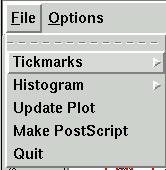
File Menu
- Tickmarks
- Checkbuttons are provided for each phase to determine if tick marks will be shown.
Tickmarks can also be toggled by pressing the "1" key for phase 1, "2" for phase 2,... Also see the Options/Configure Tickmarks menu item for information on tickmarks.
- Histogram
- This allows a histogram to be selected to be loaded
It is also possible to advance between the histograms by pressing the "n" or "N" (for next) key.
- Update Plot
- The causes LIVEPLOT to read read the current histogram again from the datafile
- Export Plot
- This offers options for exporting the plot in multiple formats. I am hoping to add more export formats eventually.
- to PostScript
- Creates a low quality PostScript file containing the LIVEPLOT output. See the Options/"Set PS output" button for where the file is created. Most unix systems are capable or printing PostScript files. On Windows, a program such ghostview may be needed to translate the PostScript to a format that can be viewed or printed.
- to Grace

- Plots can be exported to Grace, WYSIWYG 2D plotting tool for X-Windows that produces publication-quality graphics. After the plot is exported, it can be further enhanced and annotated in grace.
- Quit
- Exits BKGEDIT/LIVEPLOT.
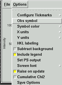
Options Menu
- Configure Tickmarks
- This submenu provides options that controls how tickmarks are displayed.
- Auto locate
- When this option is selected, tickmarks are placed in different positions for each phase, automatically, similar to how tickmarks are shown in POWPLOT.
- Manual Placement
- Tickmarks are drawn at specific heights that can be set for each phase (see below). The default is for lines to be draw from "-Inf" to "Inf", which creates lines from the bottom to the top of the plot.
- Label by name

- By default, a label "Phase1",... is displayed in the legend when tickmarks for that phase are displayed. When this button is pressed, the first 20 characters of each phase name (phase title) are used instead. This label can be edited, as described in the next paragraph.
- Phase n opts
- The options for each phase allow the line to be changed between solid and dashed, color of the line can be specified and the vertical placement of the tickmarks can be specified. The "Show Reflections" flag, set in the File/Tickmarks menu, as well as the label used for the phase can also be changed here.
- Obs Symbol (Symbol Type)
- This brings up a menu where the symbol type and size for the observed data points (and for BKGEDIT, the fixed background points) can be selected.
- Symbol Color
- The colors for all the displayed lines and symbols can be changed here.
- X units
- The x units can be selected here. The choices are "as collected" (2Theta/TOF/KeV), d-space (A) or Q (A-1)
- Y units
- The intensity values can be normalized by the incident spectrum (for energy dispersive methods).
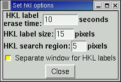
- HKL labeling
- This brings up a menu that selects
- Erase time: how long in seconds that hkl values are shown before they are erased (0 means that they are not erased),
- Label size: the size of the labels in pixels,
- Search Region: only reflections within this number of pixels of the mouse, when the "h" key is pressed (if any) are labeled,
- Separate window: when this option is selected, reflection labels are shown in a text window
- Subtract background
- The background is always shown, even when subtracted
- Include legend
- The legend is the optional box in the upper left that defines the plot entries
- Show [Hide] Cursor Position
- This turns Cursor position display on and off.
- Set PS output
- For UNIX this allows the file to be sent directly to a printer or can be saved in a file. For Windows, a file must be written.
- Set screen font
- This option is used to control the font used for menus, graphics and other aspects of windows.
- Raise on update
- This causes the plot to be placed on top of other windows, if partially obscured, when the plot is updated. At this time, this option does not work in Windows-NT and -2000.
- Cumulative Chi2
- The causes the Cumulative chi2 function to be displayed (as presented above).
- (obs-calc)/sigma
- The causes the (yobs-ycalc)/sigma values to be displayed (as presented above).
- Save Options
- Causes many of the options set in this menu to be saved in the .gsas_config (or c:\gsas.config) file.
Customization of LIVEPLOT & BKGEDIT
The localconfig and .gsas_config (or c:\gsas.config) files are read, if present. The following variables control how LIVEPLOT, and in most cases BKGEDIT, function and can be customized by changing their values in the localconfig and .gsas_config (or c:\gsas.config) files.The following variables are written to .gsas_config (or c:\gsas.config) when "Save Options" is used. These variables are all set from the GUI and therefore do not need to be edited manually.
- peakinfo(flagn)
- These variables define if peak positions will be shown for reflections in phase "n". Reflections will be shown if the value is non-zero.
- peakinfo(colorn)
- These variables define the default colors for reflections in phase "n"
- peakinfo(dashesn)
- These variables define if peaks will be dashed for reflections in phase "n" (UNIX only). Lines will be dashed if the value is non-zero.
- peakinfo(minn) and peakinfo(maxn)
- These variables dictate the placement vertical position for reflection markers, when manually placed (see expgui(autotick), below). To draw to the edge of the screen, use -Inf and Inf.
- graph(printout)
- This is set to 1 if PostScript files will be printed and 0 if they will be written to disk (for Windows all files should be written to disk).
- graph(outname)
- This is the default for the file name used when PostScript files will be written to disk.
- graph(outcmd)
- This is the default for the command used to print PostScript files (Unix only).
- graph(legend)
- Sets the default value for display of the legend in LIVEPLOT and WIDPLT.
- graph(autoraise)
- This option shows up in the options menu item as "Raise on update." When set to non-zero, the LIVEPLOT window is raised (placed on top of any other overlapping) windows each time it is updated. This option does not seem to work in Windows-NT, but this may depend on the version of Tcl/Tk.
- peakinfo(obssym)
- Symbol for observed data points. Valid choices are square, circle, diamond, plus, cross, splus and scross.
- peakinfo(obssize)
- Size for the symbol for observed data points. A value of 1 corresponds to about 1/8 inch (about 3 mm).
- expgui(pixelregion)
- When hkl values are loaded (using tcldump) and reflections are labeled, reflections can be labeled using a Shift-Left-Mouse click. All labeled reflections within expgui(pixelregion) pixels of the mouse position are assumed to be overlapped and are labeled.
- expgui(fadetime)
- The time in seconds before reflection labels are removed. A value of zero means that reflections must be deleted manually (Shift-Right-Mouse). (Mac: Shift+Apple+click)
- expgui(lblfontsize)
- A size for reflections labels in pixels.
- expgui(hklbox)
- If this variable is non-zero, reflection indices are shown in a box.
- expgui(autotick)
- If this variable is non-zero, reflection markers positions are set automatically.
Interfacing External Programs
Combining LIVEPLOT with CMPR & LOGIC If you have the CMPR/LOGIC programs installed on your computer, you can use superimpose on the GSAS results the peaks for an arbitrary unit cell. If you have an old version of the ICDD-JCPDS PDF-2 powder diffraction database, (when distributed as an AIDS*83 format flat file) you can also superimpose entries from this database on the GSAS results displayed in LIVEPLOT.
When the CMPR/LOGIC program is installed in the same location as the GSAS package (e.g. /home/gsas & /home/cmpr or C:\DIFRC\GSAS & C:\DIFRC\CMPR) or if the CMPR/LOGIC programs are loaded into standard locations (/usr/local/cmpr or ~/cmpr for Unix and Mac OSX or c:\cmpr or c:\Program files\cmpr for Windows), the LIVEPLOT program will locate both programs and add an extra menu labeled "Peak Gen" to the menu bar. If the CMPR program is not located automatically, you may customize this location by specifying a value for Tcl/Tk variable cmprdir by including a line such as this:
set cmprdir C:/ncnrpkg/cmprin the localconfig, .gsas_config or c:\gsas.config files [note that forward slashes ("/") should be used here, even for windows.]The "Peak Gen" menu will have either or both of two entries "Display a cell" and "Plot ICDD Entry", depending on what software is located. The "Display a cell" option produces a window similar to the Edit Cell feature in CMPR where allowed reflection positions are displayed for a set of unit cell parameters and optionally a space group or extinction conditions. The "Plot ICDD Entry" provides a window similar to the LOGIC interface in CMPR where ICDD searches may be conducted. From the resulting list of matches, selected entries may be displayed.
Note that these routines display peak positions in units of 2Theta, Q or d-space. If you are using TOF or EDS data, you must select Q or d-space display in LIVEPLOT. If you are using 2Theta, you must supply the correct wavelength.
Note that a version of both EXPGUI and CMPR/LOGIC from November 2003 or later must be used for these features to work.
EXPGUI top Next page
(EXCLEDT)Previous page Comments, corrections or questions: crystal@NIST.gov
Last modified 25-January-2007 by website owner: NCNR (attn: Craig Brown)
$Revision: 1.17 $ $Date: 2007/01/17 04:44:31 $