|

|
|
| Home | Live Data | Instruments | CHRNS | Proposals |
In situ tomography of an operating proton exchange membrane fuel cell at NIST
Researchers at the NIST Neutron Imaging Facility (NNIF) have acquired the first in situ tomographic (3-dimensional) images of an operating proton exchange membrane fuel cell (PEMFC). With this new capability, the NNIF is helping spur the development of PEMFC by unambiguously distinguishing the key components of the PEMFC: the membrane electrode assembly (MEA), the anode gas diffusion medium (GDM), the cathode GDM, and the respective gas flow channels. More information.
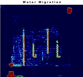
By using the exquisite sensitivity of neutrons to water (less than 1 microgram is observable), we can now see the three dimensional water distribution in a fuel cell!
The PEMFC is a leading candidate to power automobiles in the hydrogen economy. Key to its successful deployment is water management, a delicate balance between properly hydrating the MEA and keeping the GDM pores free of water to allow efficient gas flow to the MEA. Up to now, neutron imaging has been two dimensional (2-D) radiography, which measures the sum of the water in the anode, cathode and MEA. With neutron radiography, PEFMC developers could see in real time the 2-D motion of liquid water in the PEFMC. We illustrate 2-D imaging in the following figure and movie.
Click on image to start movieThe figure at the top of the page, and movie below demonstrate the power of tomography, i.e., 3D imaging, to visualize and measure the water distribution in the through-plane direction of a PEMFC, overcoming the limitation of radiography. Surprisingly, the water content of the cell peaked in the anode for the chosen materials and operating parameters! More importantly, the primary water transport mechanism in the GDM can be determined from the detailed shape of the water distribution. With such fundamental knowledge, models of fuel cells can be validated as well as the optimization of materials and operating conditions to control the water distribution. In the movie below, the components of the cell are clearly visible through neutron tomography. The grey portions are the aluminum and plastic tube inserts, and are removed. The active area of the cell is slowly built up, starting from the anode gas flow channels (the ribs of blue). The anode GDM, still shown in blue, is fairly homogenous, in each slice. The MEA is shown in purple, and as it is only one slice thick is quickly covered by the cathode GDM in yellow. Finally, one sees the cathode flow channels. (This work has been carried out in collaboration between NIST and General Motors.)
Click on image to start movie
Last modified 20-July-2007 by website owner: NCNR (attn: Bill Kamitakahara)