|
Device
Closed Cycle Refrigerators |
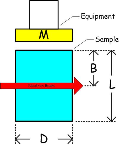
D
max. diameter mm (inches) |
B
distance to beam* mm (inches) |
L
max. length mm (inches) |
M
mounting surface description** |
|---|---|---|---|---|
|
DCS-CCR (low and high temp.) (standard CCR w/diff. outer cans) |
71 (2.8) | See DCS User Guide | See DCS User Guide |
4-bolt circle 1.75 inch diameter #10-32 tapped |
| CCR (low and high temp.) | 71 (2.8) | 44 (1.75) | 86 (3.4) |
4-bolt circle 1.75 inch diameter #10-32 tapped |
| TLCCR-Long | 57 (2.25) |
45(1.75) ± 38; 1400 (55.14) from top |
146 (5.75) |
5/16"-18 stud; 3/8" long |
| TLCCR-Short | 57 (2.25) |
45(1.75 )± 38; 943 (37.14) from top |
146 (5.75) |
5/16"-18 stud; 3/8" long |
| TLCCR-DCS | 57 (2.25) |
68 (2.66) ± 38; 1424 (56.05) from top |
178 (7) |
5/16"-18 stud; 3/8" long |
| TLCCR-HFBS | 57 (2.25) |
45(1.75) ± 38; 1400 (55.14) from top |
118 (4.65) |
5/16"-18 stud; 3/8" long |
|
Room Temperature Mount
(Normally used for aligning a sample) |
N/A |
44 (1.75)
UP from mounting surface |
N/A |
4-bolt circle 1.75" diameter #10-32 tapped (Same as above except inverted) (e.g. mounting surface is under sample) |
| Return to Top | ||||
|
Device
Liquid Helium Cryostats |
D
max. diamter mm (inches) |
B
distance to beam* mm (inches) |
L
max. length mm (inches) |
M
mounting surface description** |
| OC-DCS | 69 (2.72) | 1360 (53.54) from top | 140 (5.51) |
5/16"-18 stud 3/8" long |
| OC-HFBS | 45 (1.77) |
1304 (51.3) from top
+ 4 mm O-ring |
160 (6.3) |
5/16"-18 stud 3/8" long |
| OC-50 | 49 (1.93) |
942 (37.09) from top + 4 mm O-ring |
128 (5.05) |
5/16"-18 stud 3/8" long |
| OC-70 | 69 (2.72) | 942 (37.09) from top | 150 (5.9) |
5/16"-18 stud 3/8" long |
| OC-100 | 99 (3.90) | 1192 (46.93) from top | 192 (7.56) |
5/16"-18 stud 3/8" long |
| OC-SANS | 69 (2.72) | 930 (36.614) from top | 140 (5.51) |
5/16"-18 stud 3/8" long |
| ICE OC (50mm) | 49 (1.93) |
1305 mm (flange to beam center)
+ 4 mm O-ring |
102(4) 1372 mm (flange to bottom of well) |
stick has 5/16"-18 stud 3/8" long use with ICE dil fridge or with Oxford dil fridge insert |
| Oxford dil fridge with ICE OC | 33(1.3) | 55(2.16) | 90(3.54) |
5-16"/18 threaded hole 3/4" deep |
3He Big Blue(details) SD-55 |
81 (3.2) | 38 (1.5) | 152 (6) |
4-bolt circle 1.75 inch diameter #10-32 tapped |
|
3He Dipper (detailed pdf) used with 7T magnet |
70 (2.8) | 44 (1.75) | 88 (3.45) |
1.5" diameter copper plate with a 5/16"-18 threaded hole 1/4" deep |
| 3He Dipper with 70 mm OC | 57 (2.25) | 38-76 (1.5-3) | 102 (4) |
2.125" diameter copper plate with a 5/16"-18 threaded hole 1/4" deep |
| Return to Top | ||||
|
Device
Furnaces |
D
max. diamter mm (inches) |
B
distance to beam* mm (inches) |
L
max. length mm (inches) |
M
mounting surface description** |
| CTG Furnace | 71 (2.8) | 44 (1.75) | 86 (3.4) |
4-bolt circle 1.75 inch diameter #10-32 tapped |
| BNL-Air/Vac furnace | 84 (3.313) | 25.4 (1.0) | 95.25 (3.75) |
NOTE: bottom mount (below the beam)
4-bolt circle 1.75" diameter #10-32 tapped |
| HFBS 1400 C Furnace | 45 (1.77) | 1304 (51.3) from top | 160 (6.3) |
M8 stud 7 mm long |
| 1600 C General Use Furnace | 42 (1.65) | 409 (16.1) from top | 100 (3.9) |
M8 stud 7 mm long |
| Return to Top | ||||
|
Device
Superconductiong Magnets |
D
max. diamter mm (inches) |
B
distance to beam* mm (inches) |
L
max. length mm (inches) |
M
mounting surface description** |
| 7T SCM with TL-CCR insert | 47 (1.85) |
44 (1.75) 1753 (69.2) from well top |
1795 (70.67) from well top |
5/16"-18 stud 3/8" long |
| 7T SCM with CT insert | 71 (2.8) | 44 (1.75) | 85 (3.3) |
4-bolt circle 1.75" diameter #10-32 tapped |
| 7T SCM with 3He Insert | 70 (2.75) |
38 (1.5); 873 (34.375) from top |
87 (3.42); 84 (3.30) after adapter to standard CCR mount |
4 bolt circle 1.06" diameter #4-40 tapped |
|
9T Horizontal Field SCM transverse or longitudinal |
28 (1.1) | 38 (1.5) | 53.3 (2.1) | 5/16"- 18 stud or tapped hole |
| 10T magnet with 1K stick | 49 (1.93) |
44 - 70 (1.73 - 2.76) 1322 mm (top flange to beam center) 1326 mm (top of O-ring to beam center) |
164 - 192 (6.45 - 7.56) 1448 mm (top flange to Bottom of well) 1452 mm (top of O-ring to Bottom of well) |
1.43" diameter copper plate 5/16"-18 threaded hole 1/4" deep |
| 10T magnet with ICE dil fridge (detailed pdf) | 33 (1.26) | 55(2.16) | 90(3.54) |
5/16"-18 threaded hole 5 mm deep |
| 11T SCM with dil fridge |
25 (0.98) top loading 48 (1.90) bottom loading |
60 (2.36) |
85.34 (3.36) top loading 250 (9.84) bottom loading with 35 mm, 0 o gap |
5/16"-18 stud 0.26" long |
| Oxford Dil fridge insert with 10T magnet Lemon | 33 (1.3) | 72 (2.83) | 90 (3.54) |
5/16"-18 stud 0.26" long |
| 15T magnet 1K stick (detailed pdf) | 15 (0.59) | 82 - 134 (3.23 - 5.27) | 147 - 199 (5.79 - 7.83) |
5/16"-18 stud 0.26" long |
| 15T magnet with Oxford Dilution Fridge (detailed pdf) | 10 (0.39) | 40 (1.575) | 100 (3.94) |
M6 threaded hole 10 mm deep |
| Return to Top | ||||
|
Device
High Pressure |
D
max. diamter mm (inches) |
B
distance to beam* mm (inches) |
L
max. length mm (inches) |
M
mounting surface description** |
|
NG7 Reflectometer 20.7MPa
Heated Pressure Vessel for Thin Films |
76 (2.99) Max
Wafer Diameter |
N/A | N/A | N/A |
| 400MPa Aluminum Pressure Cell in 50mm O.C. | 8 (0.31) |
89(3.51)
±25 mm 974 (38.35) from top |
45 (1.77) |
5/16"-18 stud 3/8" long |
| 400MPa Aluminum Pressure Cell in Top Loading CCR | 8 (0.31) | 1400 (55.12) from top | 45 (1.77) |
5/16"-18 stud 3/8" long |
| Return to Top | ||||